Showing posts with label project. Show all posts

The project that started this whole new home brewery was the modified "brewhouse".

When I started brewing I used a cajun burner with one pot. Since I am not a welder by any means I needed to have someone do the fabrication when I stepped to a single tier all grain system. Brad, is a friend of a friend who last year helped me construct this single tier brew scuplture.

Realtive to the new system is was very simple, quick disconnects, one pump and three 55k btu burners.

The new system about 1/3 of the way through the modications. Once it is done it will be entirely hard plumbed, have two pumps (one for sparging and the other for wort transfer), HLT heat exchanger for step mashes, inline temp readings, several polycarbonate sight glasses, an expandable / swinging control panel supprt, a tipping mash tun, integrated plate chiller and a way to reuse the hot water from the chiller. So I guess this brewery will be "green" in the way it conserves water.


These pics include one of Brad who has done a very good job of coming up with problems with constructing the brewery. More pictures will be included as Brad's part is done and as we hard plumb it.


Read more ...

It wasn't pretty but... What did you expect from a beer that has been "conditioned" for 4+ years.

If you have tried this beer post your comments about your experience.... That is if your still alive to talk about it.

Checkout the video review.

Read more ...

We made a blackberry lambic recipe in the summer of 2004. We followed the recipe to the letter and like some other things in life my gut did not feel right following the recipe exactly. However, I thought "we have never have made a recipe like this maybe I should just do it". So we did. We added a second yeast addition, just like the recipe said and that is where I believe we went wrong.

So fast forward to four years later, and how has it aged??

It has decent head retention, a light mouth feel and a light sweet flavor. HOWEVER, this overwhelming yeast taste beats down all the other flavors. It is kind of embarrassing to talk about but twice now when I follow a recipe that does not sound completlely in line with a style it has not turned out the way we like.

Ira has the video of us tasting the batch. I will ask him to post it.
Read more ...

We (Adam, Ira, Tobias, and Matt) did a fair amount of work on the brewery components tonight. Pictures will follow here in a few days.

We have most of the cold box completed we only need to caulk a few seams, paint the outside of the box and put on casters and affix the heat exchanger to the inside of the box.

We also started the cart that the glycol chiller will sit on. This will be somewhat complex in order for the glycol reservoir not to leak.

However, the most interesting piece thus far is the "Brain" of the fermentation process which Ira is building and programming entirely from scratch. We are using a touch screen to control and monitor the process. At this point we will be able to program manually or use preset modes for the temperatures and times for fermentation.

This is a lot of information but I promise to include video and pictures to make the whole concept more intriguing.

Later....
Read more ...

Rain is great for the growth of our hops but we cannot work on the brewery then...what a dilemma.
Sent from my Verizon Wireless BlackBerry
Read more ...


Here are a few pics to update the Glycol Chilled Conical. We are improving the straps to hold the coil against the bottom of the cone. We were torn on where to put the coil for two reasons. One the Blichmann Conicals do not allow you to place coils around the top part because of how the legs are attached, and Two because we will not always be doing 21 gallon batches most of the test batches will be at most 5 gallons. I have to say that the construction of the Blichmann conicals is very high quality, exellent job John! I included the picture of the cold box again because that is where we are placing the conical within the brewery. I have to say it looks tiny on top of that box....
Read more ...


This is the physcial construction part of the cold box. Ira is doing a great job of the automation and control side.


I included some basic pictures of the framing and will add more as we go along. The frame uses 1/2" plywood and 2x4's to create the backbone of the structure. Essentially it will be a box within a box. The inner box consists of 2" Dow Blue foam and the inner most liner is made up of FRP panels for durability and easy clean up.


To cool the box we are using between 2 and 4 120mm fans to circulate air over a Haydens 405 Transmission cooler that will be hanging from the ceiling of one end of the box.


Just a tip when constructing a cold box with Liquid Nails adhesive. When applying it above you be very careful how quickly you sit up. That stuff is a pain to get out of your hair.
Read more ...


I wanted to include some pics of the first year hops. We purchased rhizomes back in March but they were not mailed to us until the 2nd week in April so we were rushed to get them in dirt. It is obvious which of the rhizomes was the largest. One of the roots is already creating a 12" bine.
The new hop rhizomes for 2009 include Nugget, Glacier, Golding, Mt. Hood (by far the largest) and Cascade. Can't wait to try some of that Nugget in one of our brews.
Read more ...


Last Saturday, May 9th, I went to check on the hops we are growing. There is both first and second year plants that we are growing at a local nursery. The first year plants are still in the greenhouse and the second year plants are on a trellis that we put together outside. The seond year plants went from 12 inches to up to 7 feet in those 12 days of rain. The ironic part is that the hops outgrew the weeds around them, grew across the tops of the weeds and then grabbed on the to first vertical surface they could find to grow upwards. So what did I do for three hours? Seperated weeds from hop plants. I have included pics. I know it is really hard to tell weeds from hop plants but I have to mow around them and put down some kind of weed control.


Read more ...

I feel as though an insane amount of planning has gone in to putting our ultra home brewery together. Each person that is contributing to the brewery has their own specialty. Today I met with Brad, who is fabricating and welding the core of the brewery. I plan on bringing him in as a part of this blog in the future. I wonder how many other homebrewers have felt this way as they plan an exciting project like this. You feel as though you have done a ton of planning and things are slowly coming together but there is a great amount of anticipation and excitement as we proceed. One of the items that is on my punch list is posting some of the pictures that I we have taken along the way.
Read more ...

A few of the other guys have tackled the task of construction of the brewery and i have concentrated on the automation of the fermenation process. So far i have created the logic which will be used for both the cold box and the Conical Fermenter controlling the heating and cooling process.

The idea is to make the system as flexible and easy to use as possible. To do this 2 variables will be used at all times to define if the system will be cooling, heating, or nothing. The logic is is shown below:


Both the Cold Box and the Conical Fermenter will be controlled separately. By controlling these process separately we will be able to ferment different types of beer at the same time. Because a PLC will be used to control this process it should be easy to track where each beer is in the fermentation process. The Control logic which will control the heating and cooling pumps is as follows:


This is the basis of what is needed to brew different beers. This logic will always be used regardless of the stage of the brew process Primary, Diacetyl Rest, Crash, Secondary. I will followup with the diagram which will show each of the process steps in a later post for now we have temperature control... O, yea not to mention the data logging. The data logging will be essential so that we understand what a beer experienced during the fermenation process. In logging this information we will be able to re-create a beer over and over again.
Read more ...

So it's been a few weeks sense the planes where posted and we have made some progress and i have just been slow to post it. The Cooling Coils have been placed on to the Conical or as i like to call it 27 Gallons of goodness. For this 50' of flexible copper tubing was used to form around the base of the conical.

We chose to coil the base of the conical rather then the top so we could make a smaller batch and still cool the system. The Fermentation process should agitate enough to circulate larger batches even with the coils placed on the lower part of the conical. If needed a second set of cooling coils could be added to the top of the conical and could be driven by a third pump allowing cooling process to happen faster (if needed). This will all be controlled by a PLC so it should not be difficult to control the third pump.

It was tricky warping these coils around the base of the conical as it is cone shaped and it took some time to make sure we had good contact between the coils and the conical. After it was warped tension bolts used to hold the coils in place and keep them firm to the conical.

Check out the process in the following video:
Read more ...


My fist adventure in radio! I started off by building a Hartley oscillator with one transistor and then amplitude modulated a signal with a second transistor. I then built an AM receiver schematic I found and calculated the tank circuit for the 50 MHz band.

Understand that this transmitter is extremely simple and haphazardly thrown together, it does not transmit any further than across the room but it is useful for understanding the basic concept of a transmitter.


AM Transmitter Schematic
(Q1 makes the Hartley oscillator, Q2 amplitude modulates the signal. It's only broadcast across a room. To increase power you would need to add some amplification. You may find this helpful for calculating the resistance values needed)

AM Receiver Schematic
(I recommend replacing the 120k
regenerative feedback resistor with a variable resistor. I used 2N3904 transistors in my build)

The Tank Circuit

The operating frequency of the Hartley oscillator and the frequency tuned in by the receiver is determined by the inductor (L) and the capacitance (C) values in the tank circuit.

Explanation of a "tank circuit".

In my circuit the variable capacitor's max capacitance is at 265 pF (estimated 290 pF to account for some stray capacitance) and the coils are roughly 1.746 uH (Micro Henrys). Turning the variable capacitor lowers it's capacitance and thus increases the resonant frequency.

I made the air-core inductor out of a .25 inch diameter soda straw.

Specs:
Diameter: .25 inches
Length: .75 inches
Turns: 31


This equation can be used for calculating the dimensions of an air-core inductor,


Where,
  • L is inductance in uH
  • d is coil diameter in inches
  • l is coil length in inches
  • n is number of turns.

I found this air-core inductor calculator to be a very handy tool for designing coils.


Calculating Inductance Needed

To calculate the inductance L (in mico Henrys) needed you will need to know 2 things. What frequency you want to operate in (I chose 50 MHz because its in the amateur band) and your maximum variable capacitance (265 pF + 25 pF estimated stray capacitance = 290 pF)

The easy way to calculate this is,


So using my values as an example,


Which comes out to,

Read more ...

A while back I put my email in for a chance to be a beta tester for Quake Live. Long since forgotten I got an email today asking me to try it...

Quake Live is a free (ad-supported) browser based first person shooter in development by id Software. It only supports Windows right now (IE and Firefox) but will eventually support Linux and Mac.
No word on the release date yet but it seems to be well on its way.

To get started I had to make an account and download a 3.78 MB plug-in. I was greeted by a friendly tutorial talking me through the game.. I promptly skipped it. Starting an online match was quick, all the matches and settings are selected through the web browser. The game is rendered in a little box which can be made full screen; I'm happy to say that it supports wide screen resolutions (that's better than Battlefield 2!).

Once I started playing I noticed that it was pretty much Quake 3 loaded off a server. The textures and models may be a little bit compressed but all of the guns, maps, and game types are very close to the same. The graphics are decent, nothing stunning but something that will play well on older computers. I can see this being very useful for getting my online FPS fix when I am away from home.
Read more ...

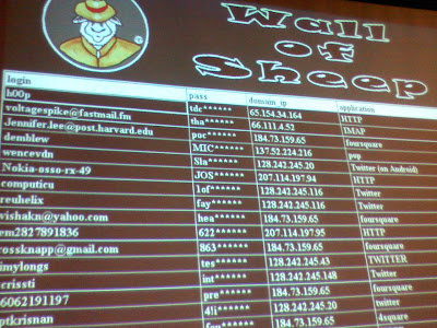
You should always be careful when connecting to a public WiFi connection, you don't want to end up like these poor saps at the Defcon convention.

I'm sure you have found yourself in a situation where you had an overzealous network filter block websites on a public connection (like at a library, work, or school). Or perhaps you don't quite trust the connection you are on?

If you have a Linux box at home that you can SSH into, you can set up a socks proxy to tunnel firefox over an SSH connection. To anyone else it will appear as if you were surfing from your servers connection.

The command is:

ssh -D 8080 user@host -N

(This will work with putty on windows too)

Leave that terminal running in the background then in firefox go to...

Tools > Options (Edit > Prefrences in Linux) > Advanced > Network > Connection Settings

And set up a manual proxy configuration under the SOCKS Host to connect to localhost (IP: 127.0.0.1) and port 8080.

You can also set up Pidgin to use a SOCKS proxy in the same way for more secure IM conversations.

Cheers.
Read more ...

Well, today is the day that the small brewery, in a small town, in an even smaller garage started... to get a bit bigger (yea we had a smaller brewery before). To make the brewery bigger plans had to be made. We needed a new brew process capable of brewing higher volumes of beer and a new fermentation process capable of creating more consistence results.

The new brew process design provides the ability to create a continues brew process by breaking the system into three parts the Hot Liqueur Tank (HLT), Mash Tun, and Boil Kettle. This new process also contains a CIP (Clean in place) system making cleanup easier (we all know this is the worst part of homebrew). Finally the heating of the Mash Tun is done by using the hot water from the HLT. This should create an easier system to deal with as there should be no worries about burning the mash killing the batch.


The new fermentation process will be controlled by a PLC. This will use two PID loops which will read the temperature of the Cold Box and the Fermentor. These PID loops will trigger heaters and coolant. pumps if needed to keep the brew at the correct temperature throughout the process.


So, plans have been made now all we have to do is build it.

Let the Homebrew Project begin!!!
Read more ...

This tutorial assumes you are using Debian based linux, such as ubuntu, and you have a server set up with root privileges on a home connection.

Update: Your router might already have Dynamic DNS functionality built it, specifically for the DynDNS service. If you can use that instead it will save yourself a lot of trouble! If not, read on and good luck :-)

DNS stands for Domain Name System, it is the service that allows you to go to google.com instead of having to remember google's IP address. A Dynamic DNS service will accept a change in IP address for a domain name. So instead of remembering your latest IP address assigned from your ISP to connect to your home server we will only have to remember one name, for example myhomeserver.dyndns.org. The server will then report any IP changes to the Dynamic DNS service.

There are a number of free Dynamic DNS services out there, for this tutorial we will be using DynDNS.

Head over to http://www.dyndns.com/ and enter in a name for your server.


You will then need to make an account with Dynamic DNS. Once you are finished it should set an IP address from where you logged in from by default. Now we are going to get your Ubuntu server to check if there is a change in IP address and if so log into your DynDNS account and report the change.

To accomplish this we are going to use the ddclient program.

First lets get ddclient from synaptic; execute this command:
sudo apt-get install ddclient

It will then run through a command line based installer and ask you a few questions to set up a basic config file. Answer all the questions it asks you, the DynDNS hostname you set, your DynDNS username and password, etc.

The tricky part is when it asks, "Enter the interface which is used for using dynamic DNS service."

If you are not behind a router or a firewall you can simply enter: eth0

But in my case I am behind a router so I cannot see what my global IP is, so I am going to use another server that will check the IP for me.

So if you are behind a router just skip this question and we will fix it manually in the config file later.

After synaptic is done installing ddclient we are going to have to manually edit the config file and add a few things. For this tutorial I am going to use emacs to edit the files.

Run the command: sudo emacs /etc/ddclient.conf

Your config file should look something like this:


# Configuration file for ddclient generated by debconf
#
# /etc/ddclient.conf

pid=/var/run/ddclient.pid
protocol=dyndns2
use=if, if=
server=members.dyndns.org
login=[your dyndns username]
password=[your dyndns password]
yoursite.dyndns.org


If your server is not behind a router then the use line should be set to "use=if, if=eth0".

However if your server is behind a router change this line,

use=if, if=

to this,

use=web, web=checkip.dyndns.com/, web-skip='IP Address'

And lastly put a new line that says,

daemon=600

This will tell the script to check your IP address every 10 minutes (600 seconds) using checkip.dyndns.com as a reference. If the IP has changed it will send an update to DynDNS else it will wait another 10 min and check again. The smallest value you are allowed to set for the update interval is every 60 seconds.

If you are using the emacs editor hold down the CTRL key and hit "X", then "S" to save your file. Then hold down CTRL again and hit "Z" to get back to the command line.


So your final configuration file should look something like this,


# Configuration file for ddclient generated by debconf
#
# /etc/ddclient.conf

daemon=600 #reports IP every 600 seconds

pid=/var/run/ddclient.pid
protocol=dyndns2
use=web, web=checkip.dyndns.com/, web-skip='IP Address'
server=members.dyndns.org
login=[your dyndns username]
password=[your dyndns password]
yoursite.dyndns.org


Now that we are all configured it is time to restart the ddclient program.

Cross your fingers and execute this command,

sudo /etc/init.d/ddclient restart

Assuming everything is set up properly ddclient should report any IP address changes. Now there is still one problem, DynDNS expects an update at LEAST once a month or else it will set your account as inactive. This is an issue if you keep the same IP for more than a month.

To avoid this we are going to make a cron job that will force ddclient to update every month.

Execute the command "crontab -e". You will be greeted with a simple editor. Add this on a new line,


00 00 28 * * ddclient -host yoursite.dyndns.org -force


Then hold down CTRL and hit X, it will ask you if you want to save, type "y" to say yes and hit enter.

Everything should work beautifully now!

Cheers.
Read more ...

An open source pumpkin...


Read more ...


No microcontrollers needed here! I started playing with some 7490 decade counters and decided to build a digital clock. The first trick was getting an accurate 1 second time base. There are a few options here, you can divide the 60 Hz AC line frequency (in the US) down to 1 Hz or you can build a crystal oscillator and divide that frequency down with decade counters.

I decided to take a more hacky approach and took a 1 Hz oscillator circuit out of an analog Micky Mouse clock. There are a few different ways you can wire these up explained very nicely here. With my clock I didn't have to run the outputs through diodes or transistors (each output is 1/2 Hz), connecting them directly together worked just fine. I also powered it off the 5 volt supply by using a current limiting LED across its power input, the alternative is to have a separate battery for the clock. Every quartz clock circuit is different so its something you have to experiment with on the breadboard before building!


digital_clock_schematic.pdf

The time is kept by six 7490 decade counters. The 1 Hz clock is pulsed into a 7490 wired up as a mod 10 counter (for seconds 0-9). The output of the mod 10 counter is pulsed into a 7490 wired as a mod 6 counter (for seconds 0-5). That circuit is then duplicated for the minutes (0-59). The hours are then counted by two 7490s wired up as a mod 24 counter. (0-23).

The tens of seconds are displayed by 3 LEDs in binary. The 7 segment displays are driven by four 4511 BCD-to-7 segment decoders. I needed thirty-three 100 Ohm resistors in total for all the displays and LEDs. Good luck!

Read more ...


My first version of the Internet Controled Car used a BASIC stamp to handle serial communication. This was a mundane task for a complex and expensive little microchip

This new version uses a parallel port printer cable which is controlled by a C program on the server. Using a parallel port also fixed an issue where the direction commands would get "stuck" if you hit two keys at once as the BASIC stamp code didn't have a buffer. I also mounted the components to a piece of wood and some standoffs so it wasn't a mess of wires all over the place.


The Parallel Port C Program

The parallel port program, written in C, will take a parameter to set the data lines, that is pins 2 through 9, to a logic high or logic low.

Example: ppp 1l 2l 3h 5h 8l


Here is the C source code for Linux.

#include <stdio.h>
#include <unistd.h>
#include <sys/ioctl.h>
#include <sys/io.h>

//#include <asm/io.h>
// Didn't work, replaced with sys/io.h


char *binprint( unsigned char x, char *buf )
{
int i;
for( i=0; i<8; i++ )
buf[7-i]=(x&(1<<i))?'1':'0';
buf[8]=0;
return buf;
}

int main( int argc, char *argv[] )
{
char c;
unsigned char val;
char buf[9];
int x;
if( argc<2 )
{
printf("Example usage: ppp 1l 2l 3h 5h 8l\n");
return 2;
}
if( ioperm(888,1,1) )
{
printf("Couldn't find parallel port (888)\n");
return 1;
}
val = inb(888);
printf("old = %s\n",binprint(val,buf));
for( x=1; x<argc; x++ )
if( argv[x][1]!='h' )
val &= ~(1<<(argv[x][0]-'1'));
else
val |= 1<<(argv[x][0]-'1');
printf("new = %s\n",binprint(val,buf));
outb(val,888);
return 0;
}

To compile save the above code, in a text editor, as ppp.c
Then in the command line execute,
gcc ppp.c -o ppp

And then drop the compiled executable into $/bin/ so it can be executed from anywhere as a linux command.

Flash controller code:
The flash controller is pretty similar to netcar v1, it detects what arrowkey is being pressed and sends the information to the PHP script. I did change the variables though so use the new actionscript,

Download: car_remote_pp.as

PHP
The PHP program, combined with the C program, is basiaclly replacing what the BASIC stamp did, turning pins high and low to control the relays.

The PHP program gets the command from the flash aplication and, depending on what that command is, executes the C program with the paramaters to turn the proper data pins logic high or low.

In my hardware configuration I mapped pin 2 for forward, so to make the car go forward you would execute,
ppp 1h
2l
Pin 3 is mapped to backward so I make 2 a logic low because you can't be going forward and backward at the same time.

To make PHP execute a program you put the command in single quotes, for example 'ppp 1h 2l'

Let this PHP file sit in the same directory as your flash app.

Hardware
The rest of the hardware, for me, is the same as Net Car v1 sans the Basic Stamp. You will have to find a parallel port cable to splice open and use a multimeter with a continuity check to find what wires correspond to the data pins and, of course, ground. If you can find a ribbon cable parallel port those are very easy to solder into a chip socket and can be plugged into and removed from a breadboard or another chip socket if you decide to make a circuit board.

The hardware interface to the car remote circuit will be a little bit different depending on how the remote works. I used some double pole, double throw relays, turned on by transistors, to make the connections on the circuit board, which replaced what would normally be the connections made by the controller sticks. Now that I think about it I could have just used the transistors. You may have to put a diode on the base to make sure no higher voltage can back-feed into the lower voltage TTL circuitry, because most car remotes operate on 9v. Please correct me if I am wrong!

Edit: A couple of people recommended in the comments to use optoisolators instead of relays. They draw less power off the parallel port and are simpler, and quieter, than having a transistor turn on a relay. Actually now that I think of it using relay's is probably the most ridiculous idea I have ever had! I kinda like the clicking sound though :-)

The next step is to put a mini wireless webcam on it and stream the video through a webcam service. Or you can just have a webcam look at the car in a room and drive it around with an overview.

Let me know if you complete this project successfully, take a video and post it as a video response to my youtube video.
Read more ...