Showing posts with label electronics. Show all posts


My first version of the Internet Controled Car used a BASIC stamp to handle serial communication. This was a mundane task for a complex and expensive little microchip

This new version uses a parallel port printer cable which is controlled by a C program on the server. Using a parallel port also fixed an issue where the direction commands would get "stuck" if you hit two keys at once as the BASIC stamp code didn't have a buffer. I also mounted the components to a piece of wood and some standoffs so it wasn't a mess of wires all over the place.


The Parallel Port C Program

The parallel port program, written in C, will take a parameter to set the data lines, that is pins 2 through 9, to a logic high or logic low.

Example: ppp 1l 2l 3h 5h 8l


Here is the C source code for Linux.

#include <stdio.h>
#include <unistd.h>
#include <sys/ioctl.h>
#include <sys/io.h>

//#include <asm/io.h>
// Didn't work, replaced with sys/io.h


char *binprint( unsigned char x, char *buf )
{
int i;
for( i=0; i<8; i++ )
buf[7-i]=(x&(1<<i))?'1':'0';
buf[8]=0;
return buf;
}

int main( int argc, char *argv[] )
{
char c;
unsigned char val;
char buf[9];
int x;
if( argc<2 )
{
printf("Example usage: ppp 1l 2l 3h 5h 8l\n");
return 2;
}
if( ioperm(888,1,1) )
{
printf("Couldn't find parallel port (888)\n");
return 1;
}
val = inb(888);
printf("old = %s\n",binprint(val,buf));
for( x=1; x<argc; x++ )
if( argv[x][1]!='h' )
val &= ~(1<<(argv[x][0]-'1'));
else
val |= 1<<(argv[x][0]-'1');
printf("new = %s\n",binprint(val,buf));
outb(val,888);
return 0;
}

To compile save the above code, in a text editor, as ppp.c
Then in the command line execute,
gcc ppp.c -o ppp

And then drop the compiled executable into $/bin/ so it can be executed from anywhere as a linux command.

Flash controller code:
The flash controller is pretty similar to netcar v1, it detects what arrowkey is being pressed and sends the information to the PHP script. I did change the variables though so use the new actionscript,

Download: car_remote_pp.as

PHP
The PHP program, combined with the C program, is basiaclly replacing what the BASIC stamp did, turning pins high and low to control the relays.

The PHP program gets the command from the flash aplication and, depending on what that command is, executes the C program with the paramaters to turn the proper data pins logic high or low.

In my hardware configuration I mapped pin 2 for forward, so to make the car go forward you would execute,
ppp 1h
2l
Pin 3 is mapped to backward so I make 2 a logic low because you can't be going forward and backward at the same time.

To make PHP execute a program you put the command in single quotes, for example 'ppp 1h 2l'

Let this PHP file sit in the same directory as your flash app.

Hardware
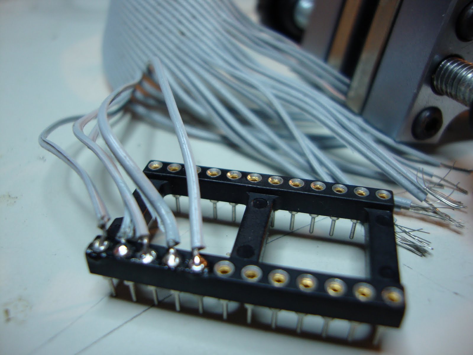
The rest of the hardware, for me, is the same as Net Car v1 sans the Basic Stamp. You will have to find a parallel port cable to splice open and use a multimeter with a continuity check to find what wires correspond to the data pins and, of course, ground. If you can find a ribbon cable parallel port those are very easy to solder into a chip socket and can be plugged into and removed from a breadboard or another chip socket if you decide to make a circuit board.

The hardware interface to the car remote circuit will be a little bit different depending on how the remote works. I used some double pole, double throw relays, turned on by transistors, to make the connections on the circuit board, which replaced what would normally be the connections made by the controller sticks. Now that I think about it I could have just used the transistors. You may have to put a diode on the base to make sure no higher voltage can back-feed into the lower voltage TTL circuitry, because most car remotes operate on 9v. Please correct me if I am wrong!

Edit: A couple of people recommended in the comments to use optoisolators instead of relays. They draw less power off the parallel port and are simpler, and quieter, than having a transistor turn on a relay. Actually now that I think of it using relay's is probably the most ridiculous idea I have ever had! I kinda like the clicking sound though :-)

The next step is to put a mini wireless webcam on it and stream the video through a webcam service. Or you can just have a webcam look at the car in a room and drive it around with an overview.

Let me know if you complete this project successfully, take a video and post it as a video response to my youtube video.
Read more ...

An electronic component is any physical entity in an electronic system whose intention is to affect the electrons or their associated fields in a desired manner consistent with the intended function of the electronic system. Components are generally intended to be connected together, usually by being soldered to a printed circuit board (PCB), to create an electronic circuit with a particular function (for example an amplifier, radio receiver, or oscillator). Components may be packaged singly or in more complex groups as integrated circuits. Some common electronic components are capacitors, resistors, diodes, transistors, etc.

Most analog electronic appliances, such as radio receivers, are constructed from combinations of a few types of basic circuits. Analog circuits use a continuous range of voltage as opposed to discrete levels as in digital circuits. The number of different analog circuits so far devised is huge, especially because a ’circuit’ can be defined as anything from a single component, to systems containing thousands of components. Analog circuits are

Digital circuits are electric circuits based on a number of discrete voltage levels. Digital circuits are the most common physical representation of Boolean algebra and are the basis of all digital computers. To most engineers, the terms "digital circuit", "digital system" and "logic" are interchangeable in the context of digital circuits. Most digital circuits use two voltage levels labeled "Low"(0) and "High"(1). Often "Low" will be near zero volts and "High" will be at a higher level depending on the supply voltage in use. Ternary (with three states) logic has been studied, and some prototype computers made.
Read more ...

I apologize in advance for the length of this "final" post - final in quotes because who knows... there may be reason to occasionally revisit this blog with updates. But before I leave and move on to the next blog project, I'd like to put down some overall thoughts on this entire experience.

1. Should be required reading for all engineering students - I feel strongly that this book should be a standard textbook for all engineering students. I wasn't in the electrical engineering department, and my electronics training was mostly white-board theory and word problems in the back of chapters. One class did get us some hands-on time with a soldering iron and some resistors, but come on! I don't think any engineer should leave school without having this level of basic knowledge.

2. Should be suggested reading for all high school students - We have these lists of books that we tell every high schooler they should read - mainly classics of literature. But how often do we provide those students who have a strong interest in math and science with a list of good technology books? This is the book I WISH I had in high school - it may very well have changed the course of my studies. I'm happy with my chosen vocation, but it took over a decade out of university for me to find the time and the right book to get my understanding of electronics to this level. So... high school teachers and parents - try to buy a few copies of this for your high school library. (I'd donate mine, but the picture I'm including here should give you an idea of how I've abused my copy - the spine is peeling away and every other page is curled and written on.)


3. The cost to learn is high - I've read some comments about Component Packs 1 and 2 that Makershed sells... and there are concerns about the extra costs involved in finishing this book and its 36 experiments. Yes, the costs are high. But I'd estimate that for less than $300 you can have everything you need, including tools, to finish this book. That's the cost of a few college textbooks these days. It's also about the same cost as a LEGO MINDSTORMS robot kit which many parents buy for kids ages 8 and up. Consider this book, all the parts, and all the tools an investment in your education (or your child's education) and dive in. The tools will always be yours (and will last if you take good care of them). I simply refuse to worry about the costs I've incurred by working through this book. The education is priceless.

4. I missed a few... argh! - A few of the experiments I never could get to work... and a few others I skipped (especially towards the end). But the important part is that I understand! I get it. I have never understood electronics before the way I do now. I am still in shock that a book like this has alluded me all these years, but I'm glad it's here now, and I have shared (and will continue to share) both the book and the skills I've learned with teachers, parents, and students.

5. Learning by Doing... and Blogging - I've always had success learning a new skill when I'm actually doing something... I think most of us will agree that this method works. But I've also learned over the years that when I write something down... either my own explanation or at least my thoughts on something... it sticks better. By sharing my experiences - and reading your feedback/comments - I get to go back through each experiment again and further cement that knowledge. Maybe you'll consider doing something like this yourself - pick a book, create a blog, and document your work as you plow through the material. Reading a book is typically a solo endeavor, but I was surprised at how many folks tuned in to follow me work through this book. It was nice to know others were doing the experiments, getting their own results, and comparing them to mine... and those who helped me troubleshoot were a huge asset that you'll never get reading a book on a couch alone.

6. Never stop learning - I've already picked my next blogging project, but for those of you not ready to leave the book after Experiment 36, you'll be happy to know that the author appears to be providing more experiments in the pages of Make magazine... I've already seen in the previous 2 issues (23 and 24) that the author has included new experiments to perform with all new components to investigate. Rest assured, if one picks my interest, I may grab it, do it, and follow up here with a post.

Just a little over a year ago (Jan 6, 2010) I began this blog with the simple goal of using it to motivate me... if I posted my work for anyone to see, it'd light a fire under me to finish. I figured if I knew people were checking in on my status, it'd be hard to quit. Peer pressure can be a great motivator.

So, here we are... Jan 15, 2011. Make: Electronics finished.

Thank you, Charles Platt, for writing the book. I think it is one of the most valuable books I've ever read.

Thank you, Make Magazine, for putting it out there and creating those components packs that have allowed many folks to perform the experiments. (I also want to thank you for supplying a nice bundle of Maker Notebooks to give away as prizes - I've kept a few for my own personal use in future projects.)

Thank you, Readers... I've enjoyed your comments, and the results and obstacles you've shared. Good luck finishing the book (if you haven't already done so). I'll continue to receive notices when you post comments, and I'll do my best to reply to them. And please feel free to share (as a comment to this post) what you'll be doing next - any books of interest? Any project kits you've found that look interesting? Let me know.

James Floyd Kelly
Atlanta, GA
Jan 2011
Read more ...

I never could get my alarm system (Experiment 20) to work as planned, so I wasn't quite sure how to handle this last exercise. I've read over it 3 or 4 times, trying to understand the theory behind it... and it makes total sense.

What I find interesting about this experiment is the how much of the circuit from experiment 20 goes away when you bring in the PICAXE chip... letting the chip handle the logic rather than all those logic chips just makes sense from both a cost perspective and a losing-my-sanity one.

Take a look at page 201 at the circuit for Experiment 20... and then jump to the bit of code that allows the chip to determine if 7-4-1 has been pressed. It's a subroutine that's called by the code on page 313...and flashes of BASIC programming started flitting through my head. I was pleasantly surprised at how I understood the code and the logic behind it. Although I haven't rebuilt the alarm, it would be a rather simple matter to gut the box and recreate the alarm using just the PICAXE chip.

Some of you (myself included) may be wondering 'Why didn't the author save the alarm project for the PICAXE section of the book?' and, of course, I totally understand the reasoning - having worked through Experiment 20 and understanding how those logic chips work, I can both appreciate the power of MCUs and the author's making us go that route and doing it "the hard way" first.
Read more ...


Exercise 35 is pretty straightforward... you can see in the photo that I've added in the trimmer potentiometer to the circuit, making certain the center terminal connects to pin 5 on the PICAXE (logic pin 2).

I ran through a few tests, taking a reading with my multimeter at various settings... the debug window screenshot I'm including here shows the potentiometer maxed out at resistance - that's what the 255 for b0 is referencing.

I took about four different readings and compared the resistance readings on the multimeter to the chart on page 307... pretty close and the deviations are certainly due to the fact that this is an analog device and I'm turning a slot screw to increase or decrease the resistance... but I totally understand why the values you'd obtain with any trimmer would be linear in nature.

The final step was to update the code to allow the LED to flash faster or slower based on the trimmer... I'm including a video here that shows those results. Pretty cool stuff. Make certain you understand that paragraph on page 309 that talks about how you can use this information to control things with major changes being done in the code versus in the circuit.

Don't forget to read over the extras on page 310 that tell you about the different features that the PICAXE chips come with... I find it interesting that this little 08M chip has the ability to generate pseudorandom numbers and tones!

Read more ...

I must have missed the memo!

In the last week, the following things have occurred:

1. Arduino The Documentary was released.

Arduino The Documentary (2010) English HD from gnd on Vimeo.


2. Make magazine Volume 25 focuses on the Arduino. (I'd estimate 50-60% of the magazine is directly related or involves the Arduino in some manner - I have the PDF/digital version on my iPad, but the print version should be out by Jan 25.)

3. Beginning Arduino from Apress hit the shelves (once again, however, I got the digital version)

4. Even The Ben Heck Show has coverage of the Arduino in this week's episode!

Given that the Arduino seems to have multiple spotlights on it for the month of January 2011, I guess this is as good a time as any to announce that when I finish the Make: Electronics book (this week, I believe) I plan on continuing forward by learning (and blogging) about my experiences with tackling the 50 projects in the Beginning Arduino book (#3 above).

Fifty projects?! I've scanned most of them and believe that I can do it... but I'm not setting a timeline and I'm most certainly not committing to doing all 50. A lot of it depends on costs (which I haven't figured out yet) of all the required components... and interest. The book looks great, but if I dig in and find myself getting bogged down or dissatisfied with the projects/book? Who knows?

That said... I've been waiting a LONG time to begin my hands-on with the Arduino. I know what it is... I know how it works... sort of. But I've never actually done anything with one. So...

I've ordered myself the Arduino Uno... and I may be ordering a few add-ons/accessories from the MakerStore shortly.

But because this is a completely different topic and book, I'll be moving this discussion over to a new blog - http://handsonarduino.blogspot.com - I've already got 2 followers, so apparently some folks have already jumped in even before the announcement.

As with this book, I'll be documenting my results - both successful and otherwise - and including photos and videos of my work. While I'm at it, I'll also do my best to build a running Google Spreadsheet that contains all the parts I've used (and where I bought them... and cost). Chime in if there's anything I've missed (or that you'd like to see me add) and I'll see what I can do...

Now... back to Exercise 35 and that PICAXE...
Read more ...


I've got a handful of videos for you here, but before I show you the final results I want to share a bit about the troubleshooting I had to perform to get the PICAXE software to properly download to the chip.

The first bit of troubleshooting was mentioned in the previous post - I simply needed to test to make certain the voltage regulator was providing 5v across the circuit... it was.

Next, I plugged in the USB cable to my laptop and to the stereo connector and clicked the Program button (to upload the program)... I got an error. (Of course.) The error window that popped up suggested I check to make certain I had the Options setting for COM port configured properly - I checked and it was (COM4) but then I noticed a button on the Option window that allows you to test the chip. The first screenshot I'm including here contains a set of short troubleshooting steps. I tested the voltage between pin 2 (the Serial Input Pin) and ground and it was 0. So far, so good. The second photo here shows that 0 volts is being read and the dark green dot (on the laptop screen) is turned off.

Next, I clicked on the dark green button (it turns to a bright green) and the voltage jumped to almost 5v (see the next photo).


So that checked out, but for some reason the program still would not download to the chip. It took me about thirty seconds to figure out the very simple problem... and here it is:

Make certain to insert the USB Cable jack into the Stereo Connector until you hear it CLICK! I didn't have it pushed all the way in (although it felt that way) and the final bit of movement requires a tiny bit of extra pressure to fully seat the jack.

After that... the program downloaded just fine. The first three videos below are all variations of the first bit of code on page 301. The first video is with the code downloaded and the USB cable still connected. Second video is with the USB cable disconnected. The third video just shows the LED blinking faster after the code has been changed.

The last video shows the results of the second program from page 304.


Read more ...


I got to work on wiring up the circuit that will be used - the most time consuming part was simply soldering some wire so it touches both leads (twice) on the stereo socket, but I think I got that part done correctly.

After wiring up the circuit, I ran a voltage test to make sure the voltage regulator was working, and one of the photos shows the 5v clearly.

There is an error in the book (verified by the errata page) with a resistor shown at the bottom of the schematic - ignore it... no resistor goes there.

Up next - typing up the code and then uploading it to the 08M.

Note: You may have noticed in the last photo a clear box of jumper wires. I purchased a box of 150+ pieces for about $10 at a nearby electronics store and I love these things - should have bought a box at the beginning. You can see in the other two photos that I've relied heavily on these pre-cut and pre-stripped wires, ignoring any sense of style when it comes to color.
Read more ...


Before you get too far into this experiment, you must make certain to install the special USB cable driver on your computer. The USB cable fools the computer into thinking it's talking to the Picaxe chip with an old serial connection (versus actual USB).

The instructions for doing this can be found on an included PDF file in the ZIP file you download, but I didn't have as easy a time installing it as the instructions suggest, so I wanted to walk through this in case there are others who encounter this issue. (Specifically, the screenshots in the PDF do NOT match what is seen on a Vista computer - they do include Windows 7 steps but my limited memory of using XP has me thinking the screenshots also DO NOT match the XP operating system - please feel free to correct me if you find the PDF is correct for XP.)

First, you need to be aware that I'm installing the driver on a Window Vista operating system, so these instructions may not match exactly with your OS... but I think you'll be able to get the basic idea of how to get around any hiccups you encounter.

The first thing you'll do (after downloading the driver - see previous post) is plug in the USB cable. My Vista laptop automatically detected it as seen in the first screen capture I'm including here. As you can see, it recognizes the cable as an AXE027 PICAXE USB device. But whereas the instructions show a nice little pop-up window that asks you to specify the location of the files, I never got this - I got an error message saying "Device Driver Could Not Be Found" and my only option was to click OK. So... it's off to the Device Manager (from a previous life as an IT consultant, I know my way around just enough to be dangerous and figure things out...)

Open Device Manager by clicking Start, and then right-clicking on Computer and choose Properties. Click on the Device Manager option in the left column of the screen. As you can see in my 2nd screenshot, there's an exclamation point next to the device telling me there's a problem.

Next, I right click the AXE027 PICAXE USB device and choose Properties. On the window that appears, I click the "Update Driver" button and a screen appears like the one in the 3rd screenshot.

Click the Browse button and find the AXE027 folder that you unzipped from the driver download. In the screen capture, click on the axe027 folder and click OK.

If everything goes as planned, you should get a screen like the 4th screenshot tellign you the driver installed correctly.

Click the Close button and if you go back and look at the Device Manager screen, you should see that the device no longer has the little exclamation point next to it like my final screenshot here.


And that's it... for the driver install. Next, I'll install the Programming Editor software and get the circuit wired up.
Read more ...


Before I get started with the circuit on page 299, I need to download and install the appropriate software and driver. The instructions for doing this are clearly explained on pages 296 and 297. I'm running Vista on my laptop, but be sure you click on the driver download that's appropriate for your operating system (Windows, Mac, and Unix all have links).

The 60MB Picaxe software is downloading right now, but when it's done, I'll first install the driver (while the USB cable is plugged in) and then the software.
Read more ...

I spent a bit of time rewiring the entire circuit for Experiment 32... taking one of my readers suggestions that the protoboard could have a bad insertion area, I moved all the wires to new locations. I then replaced the 555 chip with a new one and used my multimeter to confirm that the relay was getting higher voltage on the coil when a microswitch was pressed. Finally, as a last ditch effort after these efforts produced no change in results, I swapped out the 47uF capacitor with a 100uF... increasing the size should have increased the length of the pulse, but in this case, I get the same results - the motor reverses only when the microswitch is held down.

Argh.

Okay... so... enough of this. I may choose to come back to it at a later time (things like this really bug me) but for now it's time to move forward and get this book finished. Which leads me up to my next announcement - I've read over Experiment 33 numerous times... lost count, actually. But I've decided I'm done with robots for right now. I understand what Experiment 33 does and how it works, and, more importantly, I understand how all those 555 chips work together.

So... now it's time to get to Experiment 34. I've been looking forward to this for a while as my interest in programmable chips has been growing ever since I saw an Arduino in action controlling a remote control lawn mower (see Make issue #22). But I want to start slow... so I placed the order for all the required hardware for Experiment 34 (and 35) and it all arrived this afternoon (see the picture).

I've got 3 of the 08M PICAXE chips, the special USB cable required, and the small stereo socket. Also included in the box was a handful of resistors and misc required to properly wire up the stereo socket. I need to download and install the software specified and I'm ready to go.

Note: Inside the box, the company also sent a photocopied sheet that included a hand-drawing of the 08M wired up in a special manner, complete with resistors and voltage requirements. I'm including a close-up of that photo here, but it doesn't look complicated at all.

More to come...
Read more ...

This circuit is still driving me up the wall... I triple-checked all my connections, but I'm fairly certain the connections are done properly as the motor behaves somewhat correctly - it spins forward until a microswitch is pressed and then reverses direction... but only for a split second.

I used my logic probe to check the pulse on pin 3 but I'm honestly not 100% sure what I'm looking for...

One thing I did do that puzzles me - I unplugged the motor as it's quite loud and was making it difficult to hear the relay switching... when I did this and I turn on the power, I don't hear the relay doing anything, but when I press a microswitch, I hear the relay click (once) indicating that the coil is getting power and reversing the direction of the motor... but when I release the microswitch, I don't hear the click indicating the relay has switched back... but when I release the power button, I do hear a click. Maybe this is normal, but I'm wondering if somehow the relay is not functioning properly.

I've about decided to move on - I'll puzzle over it later tonight, maybe tomorrow... but if I can't find a solution, I'll move forward as I think I've gotten out of the experiment all I can.
Read more ...

Just an FYI - maybe save some of you some time...

I priced out the components for Exercise 34 on both Sparkfun.com and phanderson.com - summaries below. The advancedmicrocircuits.com website didn't seem to have the 3.5mm stereo socket (Figure 5-126) and their search feature just plain stinks... took me a few minutes to find the USB cable but had to search for 'picaxe usb' to locate it...

Total costs, with shipping are:

Sparkfun.com - $40.89 - this price is for 2x of the 08M chip, 1x of the USB cable, and 1x of the stereo socket adapter.

Phanderson.com - $38.35 - your price may differ as they use your zip code to estimate shipping costs... but this order comes with 3x of the 08m chip, 1x of USB cable, and 1x of stereo socket adapter.

I placed my order with phanderson.com today. I probably should have checked mouser.com and others, so if any readers do so, please share your findings - thanks!
Read more ...


Well, I finally managed to grab some time to get back to the circuit on page 277... I bought a smaller breadboard that will allow me to mount to the robot (if I can ever get this thing working) and not have to solder every component... saving me some aggravation if debugging is required.

As you can see from the video, I've made a giant step forward - the motor spins forward until either of the switches is pressed... if the switch is held down, the motor reverses direction and continues reversing until the switch is released. But...

This isn't how it's supposed to work. When the robot hits a wall or table or other obstacle and a microswitch is pressed, the robot is supposed to reverse direction for about 5 seconds (more on that in a minute) and then move forward again... the wheel mounted to the moving pivot is supposed to help the robot find a different (random) direction to move.

Now, a few things that may or may not be affecting this circuit - first, I don't have a 0.01 uF capacitor for C2 in the circuit - I have a 0.1uF ... but I do have a 47uF cap for C1. If I understand the 555 chip correctly (referring back to page 157 for monostable mode) - a 47uF cap is on pin 6... and I've tried the 100K potentiometer at both settings (using a screwdriver to maximize and minimize the resistance) but no change.

I'm going to go back and take another look at my circuit, but I've double checked all of the circuits resistor values and all my wiring of the 555 and the relay. Because the motor is spinning forward UNTIL a microswitch is pressed, I think I'm close to getting this to work... but why it won't spin in reverse for the full 5 seconds still alludes me...


Read more ...


Per Retrophile's suggested tip involving my relay being wired incorrectly, I changed the wiring and figured out my mistake (thanks Retrophile) - I assumed incorrectly that the relay's pins fit logically to the pin layout in the schematic... they don't. Going to the documentation for this particular relay verifies that Retrophile's pin layout is correct.

The two photos here show the rewired circuit - same circuit but just a slight change in photo angle for you to get a better look.

So, I've rewired the relay and as you can see in the first video below, the motor spins but the switches are still not causing the motor to stop and reverse. I used my multimeter to verify that I've got the switches wired correctly - the top and bottom pins are Normal Open (using the middle pin and bottom pin is Normal Closed and the multimeter shows a 1 when the button is NOT pressed... 0 when it is pressed). Per the schematic, we want the switches open, so I'm fairly sure I've got that wired correctly. I also replaced the 555 chip with a new one, just in case... but no luck.


So, my next step was to shoot another short video showing me using the logic probe on the 555 chip. My description here may not be 100% on the money, but as I understand the chip and the schematic, pushing a switch causes pin 2 to detect a drop in voltage... and causing pin 3 to allow current to flow (or is it just an increase in voltage - is voltage always present? Something to look into...)

As you can see from the video, putting the logic probe on pin 3 and pushing the power button causes the probe to change in pitch... that should be right. But then when I press any switch, pin 3 should change in voltage and be detected by the probe... but nothing happens. Any thoughts?

Read more ...


I will say that, up to now, I have much preferred to use AllElectronics.com versus Mouser.com - mainly because I've found Mouser to be information overload.

This morning I received an email from Mouser.com about a new web browser add-on for both IE and Firefox called the Mouser Search Accelerator... it'll basically allow you to highlight a component - a word, a part #, name, etc, - and then, without leaving the page you're on, perform a search of Mouser.com. Pretty slick, and I think I'll give it a try soon. Let me know what you think if you give it a spin.

More information on it can be found here - it is something that must be downloaded and installed on your computer, btw.

UPDATE:

Okay, I installed it on my Firefox (3.6) browser - as you can see, after highlighting an old part # from a previous post, I right click and select to search on Mouser.com - a little fly-out window appears with links to the part and a price... and look at that! The price hasn't changed since I ordered the part back in April 2010.
Read more ...


Suggestions are coming in on ways to test or fix the problems I'm encountering. Let me explain what's happening now.

I've inserted the diode that j suggested... works! The buzzing has disappeared (see video below). So we're getting close. Right now, pushing either switch (that will serve the robot as a trigger to stop and back away from an obstacle) does not stop the motor from spinning - pushing either button is SUPPOSED to cause a drop in voltage on pin 2, so I think my next step is to use a chip tester to see if pin 2 is being triggered. (Right? No?)

I'm including some pictures here - one is the schematic and the rest are close-up photos of my circuit - maybe I've got an unseen error in my wiring. Be warned - my use of the breadboard is obviously that of a newbie, so I've got wires running all over the place. If I can't figure this out soon, I think I'll start over and try to rewire a bit cleaner and closer to the layout of the schematic.

Thanks in advance for all your comments and suggestions - I love learning by doing... and making mistakes is another favorite technique of mine as I tend to remember what I did wrong versus what I did right... and that's what drew me to this book in the first place!

First video below is WITHOUT the diode.


Second video is WITH the diode.


(FYI - family visiting this weekend so I may not get much more work done on this circuit until early next week.)
Read more ...

A short update today - only a small bit of progress... let me explain.

First off, I've gotten over sharing my dumb mistakes with the world via this blog... when you decide to walk through a book and perform all the tasks/exercises/experiments and share your results, you've gotta expect to have the occasional embarassing moment. I've had plenty during my tour of Make: Electronics, and I'm not done yet...

So, here's what happened - take a look at the schematic for Experiment 32 (if you have the book)... see that 50K trimmer there and how the left side of the resistor isn't connected anywhere? That's not an error... but I thought it was! So, I just connected that end where it felt right.

And... of course... the video yesterday shows my results. So, after Mr. Platt explained this little techy bit to me, I pulled that wire and ran the circuit. The motor still spins, but THIS TIME the two microswitches, when pressed, stop the motor. Progress. But not fixed.

Pressing either of the microswitches is supposed to reverse the motor's spinning for a short period of time. But it doesn't. Instead, pressing a microswitch causes the relay to buzz LOUDLY and the motor does stop rotating... almost. If you hold down the microswitch, the motor appears to stop but in reality it still rotates in the original direction but VERY slowly... almost impossible to see. Oh, and the relay buzzes LOUDLY! Release the microswitch and the motor begins rotating in the original direction again.

So, don't connect the 50k trimmer on both ends... just the one shown in the figure. And if anyone has any ideas WHY my relay is buzzing AND why either microswitch doesn't cause a reversal in the motor spin, please let me know... I'm taking a step back to think about this for a bit.
Read more ...

I just went over to the Components Pack 1 webpage to confirm the list of components in the kit... and I was surprised to find a large number of negative reviews... after reading over them, it appears that the kit has been out of stock for just over a month (earliest 1 star review was August 21... latest Oct 1).

I'm not sure what's happening, but if you're trying to gather up the parts on your own, I've tried to include my Shopping Lists in previous posts, including part#s and sources. I may have missed a few, but hopefully there's enough information there to help you consolidate some shipping from multiple sources. (Click on the Shopping List label to the right of the screen to filter the blog and display my shopping list articles... if I've missed one, please let me know.)

I know it's frustrating - I was already well into Chapter 4 when these kits became available and it would have been nice to have all these parts together in 2 kits. But hang in there - if you've got the book and are wanting to get into it, keep in mind that the Chapter 1 exercises are low-cost, really... I'm not counting the tools such as the breadboard, soldering iron, etc... I'm talking about the components like LEDs, batteries, a few capacitors, resistors... you can easily get deep into Chapter 1 before spending a lot of money and in that time, maybe Components Pack 1 will become available. (It looks like Pack 2 is still available.)
Read more ...


Before cutting out the wood for the shell of the robot, I figured it might be wise to actually wire up the schematic first and see if I can get all the electronics to work. As you can see from the video and picture, I've managed to wire up the motor - I've got a temporary push button that allows me to provide power to the circuit. I'll get an actual on-off switch once I get the circuit de-bugged.

The circuit is definitely providing power (6V) to the motor, but the two microswitches are not working as desired. When one is pressed, it's supposed to drop the voltage on pin 2, triggering the coil and reversing the spin on the motor... but that's not happening. Pressing either switch does not reverse the motor. I'm using different microswitches than the ones seen in the chapter, but I don't think that's the issue.

I also need to get out my chip tester and make sure that voltage is detected on pin 3 that runs to the coil.

Obviously, any suggestions my readers may have will be appreciated.

Read more ...